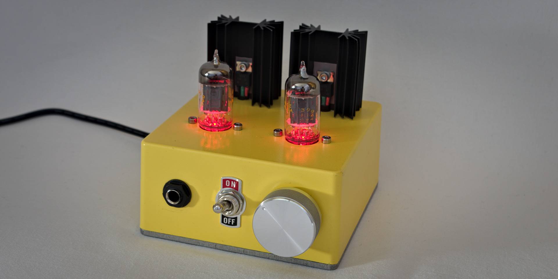
How to make a hybrid tube/MOSFET amplifier for headphones.
1 What you will need
The list of components:

or LibreOffice Calc :bill-of-materials.ods
Schema:

2 Design
Reference websites: pmillett.com1 and diyforums.org2
For “through-hole components” such as capacitors and terminals (unlike SMD3 Surface-Mount Device):
- check that the components are perfectly plated on the board for a good maintenance of them
- on a double-sided card: in the PcBnew design software (see [KICAD] (http://kicad-pcb.org) [^ 4]), make sure the pads are drawn on the correct side of the face to soldered. An error is quickly arrived!
3 Routing
The routing design is done automatically with the software FreeRouting4
- software source code: github.com5
- a tutoriel: wayneandlayne.com6
Installation script for Mageia 5 (To be adapted for other distributions with apt install … for example):
#!/usr/bin/env bash
#
# Credits: http://www.freerouting.net/fen/viewtopic.php?f=4&t=255
# (A message written by forum user "foka" on 2014-03-23)
#
# 1. Installation des paquetages:
urpmi java-1.8.0-openjdk-devel icedtea-web
# 3. Création d'un lien symbolique:
ln -s /usr/share/atnt/lib/jh.jar  /usr/share/java/jh.jar
# 2. Compilation
if javac -classpath /usr/share/java/jh.jar:/usr/share/icedtea-web/netx.jar \
        `find -type f -name "*.java"`
then jar cfe fr.jar gui.MainApplication \
    `find -type f \( -name "*.class" -o -name "*.properties" \)`
else echo "*** Some .java file was not compiled. See above" 1>&2
    exit 1
fi
# 3. Démarrage:
java -jar fr.jar
4 Production
I use a micro drill kit from 0.2 to 2 mm. I pierce all the pads with a 0.8mm drill bit.
2.1 Resin of poor quality
With a photosensitive plate whose resin is of poor quality I encountered difficulties in making it. After the engraving step, pieces of resin and copper came off!
The problem is solved with a brand plate: Mega Electronics

4.2 Fragility of the tracks
Be careful if you need to desolder/resolder a component (if like me, you correct an error), the tracks are fragile. They can be torn off as shown in the picture!

4.3 Tin solder
I tried lead-free tin soldering. Even with a 400 degree iron the solder forms a ball, it does not spread properly over the entire surface of the pad.
The problem is solved. All my soldering was done with tin/lead with an iron at 280 degrees.
Tin/lead solder smoke is harmful because of lead vapours. I purchased a portable extractor hood (ref: TOOLCRAFT ZD-153A)
 Assembly of components
4.4 The assembly
To mount the two red LED in the tube holder, I simply enlarged the existing hole with a 3mm drill bit. A glue point to hold it all together and that’s it!
 Wiring
5 Retrospective
If making a second version, I will directly connect the vacuum tube sockets to the PCB and not with cables. Similarly, I will connect the jack and the potentiometer on the PCB, but on the other side, opposite of vacuum tube sockets.