PIXEL 360, or how to keep an eye on the details!
Automated picture taking, for creating a panorama.
Click to expand the table of contents:
- Introduction
- 1 Preliminary model
- 2 Prototyping
- 2.1 The digital model
- 2.2 Parts manufacturing
- 2.3 The electronic motor control board
Introduction
During my holidays I made many panoramas of mountainous sites in the Pyrenees and in the Alps. This is how I came up with the idea of creating an automatic device to take this type of photo in order to speed up the photo taking process and improve the aesthetic rendering of the panorama The quality of the panorama is improved by reducing the bad connections thanks to a constant overlapping rate.
So I needed a system that would allow me to increase the speed and accuracy of shooting.
At first I am looking for an existing solution, but given the limitations encountered, I then start creating my own panoramic head model.
1 Preliminary model
My preliminary model is largely inspired by the project GigaPi1.
1.1 Design
To make the 2D plans of the model, I used the free software FreeCAD.
The model is made up of two plans: the chassis and the cradle.
The idea is to print the plans on a 1:1 scale on an A3 sheet to transfer them on a 19 mm thick MDF board.
Bill of materials :
- The chassis, a rigid frame that can rotate on an axis and is designed to support the cradle: chassis.pdf
- The cradle, a rigid frame designed to put a camera in place according to the nodal point : berceau.pdf
1.2 Purchases
List of supplies :
- Two MDF boards, 272 × 385 mm thickness: 19 mm.
- Two worms and Lego type toothed wheels.
- Two 5v stepper motors, integrated 1/64 reducer, reference “28BYJ-48”
- A ULN2803A stepper motor controller.
- A Raspberry Pi.
- A surveyor’s tripod.
- An rotary base for laser level (see photo).
1.3 Making
The method for cutting the frame and the cradle:
- Print the plans on an A3 sheet.
- Fix the A3 paper on a 19 mm thick medium board.
- Prick the drawing with a nail to transfer the outlines of the plan on the medium board.
- Cut out the medium board with a band saw or jigsaw following the traces of the nail tips.
 Preliminary model
 Rotary base
1.4 Engine control
The motors are connected to the pins of the stepper controller. The controller is connected to the Raspberry’s GPIOs. The Raspberry supplies 5v power to the motors and controls the motors via the controller.
I made a program in Python to drive the engines and with an acceleration curve, to prevent the engines from skidding at startup: pano.py
 Motors and controller
1.5 My feedback
I encountered some problems when I using the model. There are some steps that “jump” when the motors rotate and the head does not positioned correctly.
There are several reasons for this:
- The motors are not powerful enough to move the panoramic head despite the 1/64 gearbox.
- Gears friction is high which adds resistance to rotation.
- The structure is flexible and the structure is deformed, this slows down the rotation movements.
Les solutions que j’ai retenues sont :
The solutions I’ve come up are:
- MAke a rigid, non-deformable chassis and cradle in light metal.
- Replace the engines by more powerful ones, the choice will be based on calculations from a simulation.
- Reduce friction by using ball bearings and thus increase the precision of movements.
2 Prototyping
Based on the experience gained, I leave this model aside and start a new concept …
The chosen principle is to model the whole of the future prototype before going into production.
This allows me to make tests/errors to guarantee an optimum result.
I go through the drawing stage to validate key concepts. Then I start to make the digital model of the prototype.
 Technical drawing
2.1 The digital model
The digital model will allow me to, among other things:
- to dimension the engines
- to optimize the footprint
- to improve the aesthetics
- to make a 3d rendering to present the panoramic head on a kakemono
2.1.1 Constraints imposed
I impose the following constraints to design the new panoramic head:
- A rigid, lightweight and compact frame.
Rigid for the precision of the head’s movements. Light to optimize the size of the motors. Compact for ease of transport. - The modal point of the camera must be at the center of rotation of the panoramic. This is a prerequisite for stitching the panorama pictures, otherwise there are flaws in the final rendering.
- The panorama head is equipped with a Pentax K5 camera. The dimensional and mass characteristics of the K5 must be taken into consideration to design the panoramic head.
2.1.2 My technical choices
In summary, I make the following choices:
- Build a digital prototype to validate the design (static model): aesthetics, dimensions, positioning of the K5, engine torque.
- Realize rotation simulations (dynamic model) to validate the kinematics: find the engine torques.
- Use stepper motors (vs servo motor), to simplify the programming of motor controls (no servo loop to design).
- Use standard aluminium rails: simplify manufacturing and reduce costs, while being rigid and lightweight.
2.1.3 K5 modeling
Measurements of the DSLR case and lens :
Approx. 131 mm (W) × 97 mm (H) × 73 mm (D) for the case (excluding protrusions)
I’m trying to determine:
- The center of gravity with a homemade DIY, in order to exploit it in the digital model.
- The position of the nodal point, in order to correctly place the K5 on the axis of rotation of the panoramic head (see chapter: Search for the modal point).
2.1.3.1 Search for the center of gravity
To determine the centre of gravity it is necessary to attach the K5 by a wire which represents an axis, and to determine on this axis its position in equilibrium with the spirit level. Reproduce this on the different axes. The intersection of the axes makes it possible to find the centre of gravity.
 The search for the centre of gravity
2.1.3.2 Search for the modal point
To avoid a parallax effect, i.e. the photos do not overlap correctly during panoramic stitching, the positioning of the camera in relation to the centre of rotation of the panoramic head must be calibrated.
A common way to do it:
- Place the camera on the panoramic head.
- Place a vertical line 20/30 cm from the camera, e.g. a cocktail stick.
- Aim a very far vertical line, greater than 500m (e.g. a radio masts) so that the two lines are confused.
- Rotate the camera.
- Adjust the position of the camera so that the axes always the same regardless of the position of the camera.
- The calibration is optimal when the rotational axes of the panoramic head and the nodal point are coaxial.
For more details :
https://www.guide-photo-panoramique.com/point-nodal.html
2.1.4 Engine specifications
To carry out the kinematic modeling, I took into account the dimensions, dimension, positioning, mass and inertia of the following elements:
- Engine specifications.
- Characteristics of the rails (chassis and cradle).
- Characteristics of the fixing devices.
- Characteristics of the transmission components (pulley, belt).
- Characteristics of the K5.
To calculate the necessary engine torque, I used the “meca” software from solidworks. The variables on which I acted during the dynamic simulation to ensure that the torque is compatible with the engine :
- Place the position of the centres of gravity of the heavy elements (motor, K5) as close as possible to the axes of rotation.
- Vary the acceleration of the engines.
- Dimension the pulleys.
- Choose an admissible torque of the motors according to the supplier’s descriptions.
In conclusion, I chose a stepper motor with an epicyclic gearbox because it allows :
- To create a very gradual acceleration curve. Indeed with a reducer it takes more steps to make a complete revolution.
- Access to larger engine torque using the reducer.
- To have an “anti-return” effect. The engine does not need to be powered to lock the axis in its position.
From the simulation of the panoramic head, I get a curve representing the engine torque as a function of time. The result of the simulation shows that with a gear ratio of 50.9:1 the maximum motor torque is 40 N.cm.
 Engine torque simulation
The selected engine is:
- Type: Nema 17 (distance between fixing screws 42mm)
- Torque: 44Ncm
- Current: 1.68A
- Reduction: 50.9: 1 (step of 0.035 °)
 Stepper motor
2.1.5 Characteristics of transmission devices
The kinematic modeling, allowed me to dimension the fourth pulleys:
The two identical pulleys of the chassis:
- Reduction: 1
- Tooth profile: GT3
- Number of teeth: 42
The two pulleys of the cradle:
- Reduction: 1.62
- Tooth profile: GT3
- Number of teeth: 24 (motor) and the other 38 (axis)
 The belt
To get an accurate adjustment of the pulley and belt, the manufacturing conditions must be taken into consideration. To do this, I printed several pulleys in 3D, adjusting the dimensions of the digital model as I went along, until I got a perfect grip between the belt and the pulley.
 The cradle pulley
2.1.6 Chassis and cradle characteristics
At this stage of the study, the digital model of the panoramic head allows me to verify :
- the size of the aluminium rails of the chassis and the cradle.
- that there is no collision between the parts by simulating the movements of the panoramic head
- the overall aesthetic appearance
2.1.7 Fixing the rails
The rails are fixed together with plates and brackets made of Plexiglas, a rigid but brittle material with a thickness of 3mm. The 5mm diameter CHC nuts and screws are well suited because the nuts slide inside the rail groove.
2.1.8 Design of printable parts
When designing the parts, i.e. defining the shapes and dimensions, you have to take into consideration how they will be printed.
This is information acquired through feedback:
- The dimensions of the parts are limited by the size of the machine. In the case of the project, my 21cm X 29cm printer is suitable.
- Take into consideration the diameter of the nozzle which has an influence on the dimension of the printed object
- Do not print the whole piece, print samples to test the tolerances (e.g. testing bearing seats, nut flooding, etc.).
- Take into account external (or internal) angles. Beyond a shape having an angle of 45 ° with the Z axis (in the direction of the printing height), it is necessary to use supports.
- The supports are automatically generated by the slicing software or they have to be added during the design of the part
- Flat surfaces can curl, so it is best to ensure that this surface is in optimal contact with the bed..
- The surface in contact with the bed is smooth, there are few visible traces, which may be an advantage for the aesthetics of the parts.
2.1.9 Ball bearings
The bearings have been tightened axially using nuts or screw caps.
2.1.11 Model validation
The design stage is complete when all the points are green:
- engine-torque validation
- validation of dimensions and positioning of the K5
- aesthetic validation
 3D rendering
2.2 Parts manufacturing
The parts were made with the tools, machines and advice from the Coh@bit fablab.
The panoramic head is made up:
- of rails for the structure.
- of PMMA plastic parts or also called acrylic glass to make mainly brackets and engine mounts.
- of PLA plastic parts for printed parts: pulleys, bearing support. They are shown in red on the 3D rendering of the panoramic head.
2.2.1 Cutting the rails
I used the horizontal band saw.
2.2.2 Laser cutting of PMMA parts
The files are from Solidworks. They are exported in SVG format so that they can be imported into the software of the laser cutter/engraver. The cutting parameters are pre-configured in the machine. Cutting is very fast, the order of magnitude is a few minutes.
2.2.3 3D Printing
The stages of the digital chain :
- export the file of the part to be printed in STL format from Solidworks.
- use the Slic3r software, a slicer and export the result in g-code format for the printer.
- use the Octoprint software to read the g-code and drive the printer. Octoprint has a web interface. You can therefore control the printer remotely and monitor the printing (several hours) via video feedback.
- Octoprint communicates with an Arduino microcontroller. This one embeds the Marlin software (firmware) which interprets the g-code and it returns information on the status of the temperature sensors and the motor positions.
My recommendations:
- plan the quantity of filament necessary, so as not
- use blue masking tape, it has very good adhesion
 The manufacture of a pulley
2.3 The electronic motor control board
To design the electronic board that will drive the two motors of the panoramic head, I used the Kicad software.
This board is produced using a chemical etching process. See this link which explains all the steps: reso-nance.org
Note: To avoid using chemicals, it is possible to engrave the tracks with a milling machine (CNC). This is very well suited for double-sided boards without surface mount components (SMD).
2.3.1 The electronic board version 1
During function tests, the Raspberry Pi (RPi) burned out! This is probably due to the fact that the board was powered by the Raspberry.
From this failure, I am designing an improved version.
Disadvantages of this electronic board:
- An error in my schematic, I have an extra useless capacitor 2.
- Board power through the Raspberry
- The A4988 stepper motor controller has a maximum current of 1A and up to 2A with a heatsink.
Benefits :
- I²C protocol
- single-sided design
 The electronic board version 1
2.3.2 The electronic board version 2
I replace the A4988 controller by the DRV8825, it supports a higher current, a max of 1.5A without heatsink and 2.2A with an adequate heatsink. For this electronic board, I use a heatsink and a fan. The chosen motor needs 1.68A for optimum use.
In order to isolate the Raspberry Pi from the control board I do not use the GPIOs of the Raspberry. To do this, I mount on the MCP23008 two-chip board, GPIO extensions, which communicates with the RPi using the I²C protocol. The DRV8825 controller is connected to the MCP23008.
The power supply of the Rpi is separate from the electronic board:
- One power supply for both controllers in 12v.
- A second power supply in 5v which is regulated in 3.3v for the diodes, the MCP23008 and the fans.
 Schematic
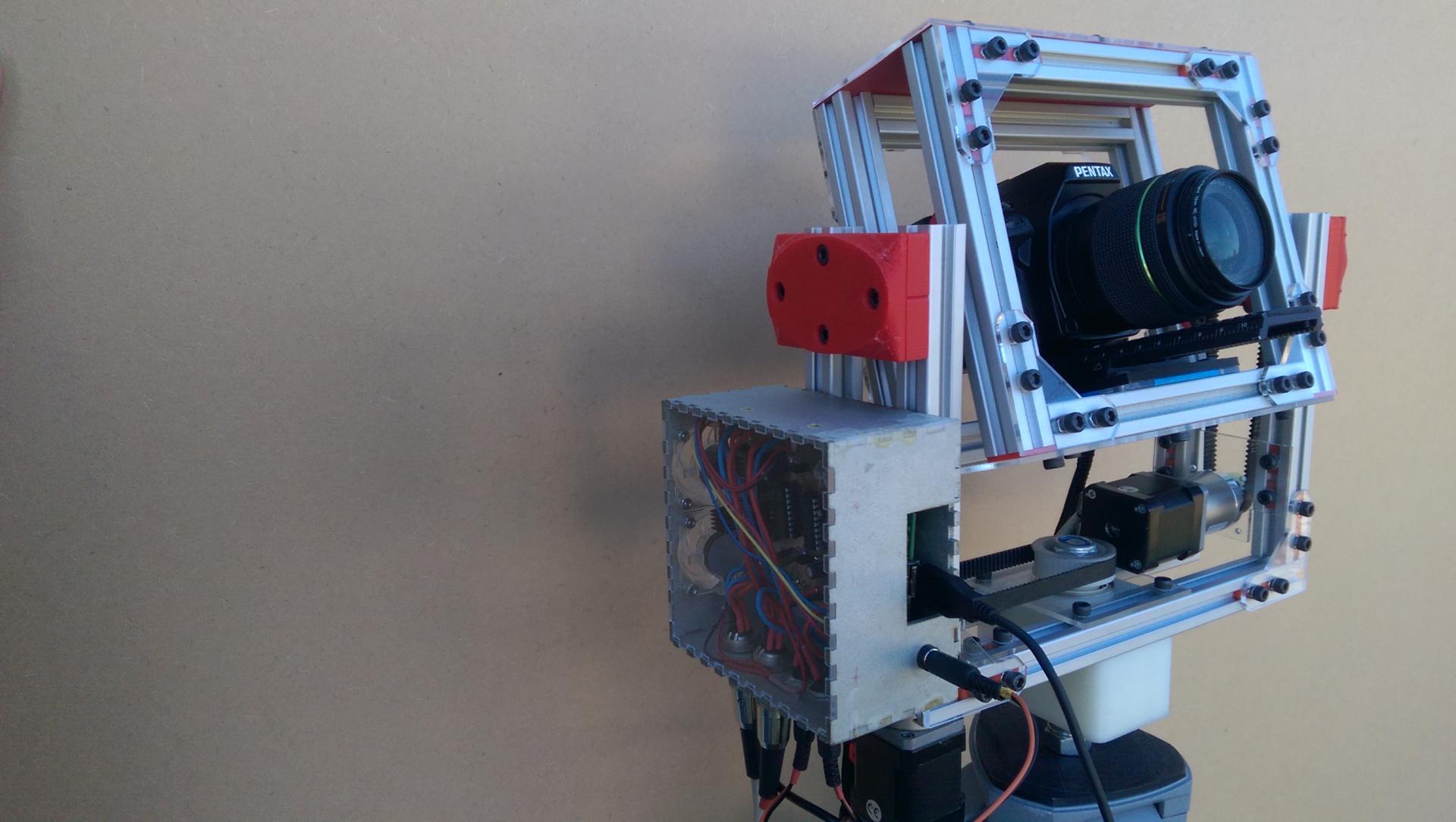
 The experimental stage
The electronic board is installed in its case. In this photo, the Raspberry is not visible, it is under the electronic board.
The case is made of MDF and the cover is made of acrylic, the whole is laser cut.
 The electronic board version 2
-
http://gigapi.blogspot.fr/2013/05/gigapi-project-by-tim-jack-stocker.html ↩︎
-
The power capacitor ensures the stability of the current, the A4988 motor controller is sensitive to peak current. ↩︎